What is an ORB Fitting?

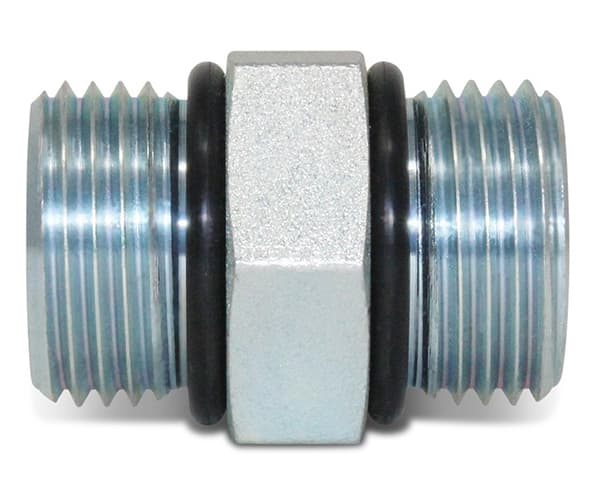
Image description: A silver ORB fitting with O-rings on both sides
Commonly knowns as the O-ring boss (ORB), these types of fittings are defined by the SAE J1926 standard. The O-ring allows for an extremely tight seal that can withstand high pressures, useful for hydraulic and other automotive applications.
Commonly known as the O-ring boss (ORB), these types of fittings are defined by the SAE J1926 standard. It defines the dimensions for both the male and female parts.
The male part consists of threads given by the Unified Thread Standard (UNF/ASME B 1.1) with a groove for the placement of an O-ring. The female part has a seat or chamfer from where the threads begin. When the two parts are connected, the rubber-like O-ring compresses between the two seats of the male and female parts. This allows for an extremely tight seal between the two parts, compensating for the dimensional variations.
Given the variation of standards employed for fluid conveyance throughout the world, one may require a fitting with ORB fittings at one end and NPT, NPS, AN, or JIS at the other. They are commonly manufactured using high-strength carbon or stainless steel to withstand the high-pressure applications they are used in.
Thread Description
The thread is defined in the format #X – YY UNF, where X is the major diameter (Dmaj) that identifies the thread length, and YY is the pitch that defines the distance between each thread. Each thread has an angle of 60O.
Dmaj is given by the following formula: Dmaj = X × 0.013 in + 0.060 till X =12, and is measured in inches while the pitch is defined by thread per inch (TPI). For X > 12, X itself defines Dmaj. Below are some common thread sizes.
